Posts

Showing posts from June, 2021

Open loop Alarm with Raspberry pi pico

Image
#This is a micropython Script of an open loop Alarm   from machine import Pin,PWM from utime import sleep button_NC = Pin(16,Pin.IN,Pin.PULL_UP)#NC PB to Gp16 and GND via 10K resistance led = Pin(15,Pin.OUT) buzzer = PWM(Pin(13)) while True:     if button_NC.value()==1:         led.toggle()         buzzer.freq(500)#Buzzer will start to beep according to the frequency and duty.         buzzer.duty_u16(90000)         sleep(0.5)         buzzer.duty_u16(0)         sleep(0.05)         buzzer.duty_u16(1)     else:         led.off()         buzzer.deinit()

laser beam interrupt alarm system

Image
  '''This is a laser Beam Alarm System. (if any oject interrupt the lazer beam to the ldr sensor- an alrm will trigger)''' import utime from machine import Pin, PWM from utime import sleep buzzer = PWM(Pin(13)) led = Pin(15,Pin.OUT) laser_sensor = machine.ADC(26) while True:     print(laser_sensor.read_u16())     utime.sleep(2)                              if laser_sensor.read_u16()<= 5000:#if laser sensor value is less than or equal to 5000         print(" Alarm Triggered")         led.on()         buzzer.freq(500)         buzzer.duty_u16(90000)         sleep(0.9)         buzzer.duty_u16(1)         sleep(0.01)         buzzer.duty_u16(0)     else:         print("System Normal")         led.off()         buzzer.deinit()

Button Pressed Buzzer Tone

#This is an example project to Control a buzzer with push button  from machine import Pin, PWM # from machine module import Pin class from utime import sleep # from utime module import sleep function button = Pin(16,Pin.IN,Pin.PULL_UP)# At initial condition,Pin 16 will interally will go High or(1) '''create a variable 'button' and declare the Pin umber and assigned as an INPUT,Internaly Pulled UP (Connect push button in between GND and Pin#16)''' buzzer = PWM(Pin(13))# Created a variable 'buzzer' and declared PWM Pin#13 while True:     if  button.value() == 0:# if button pressed-Pin 16 will contact with GND,so value will go-(0)         buzzer.freq(500)#Buzzer will start to beep according to the frequency and duty.         buzzer.duty_u16(90000)         sleep(0.5)         buzzer.duty_u16(0)         sleep(0.05)         buzzer.duty_u16(1)     else:         buzzer.deinit()# if button not pressed,Buzzer will stop

Finding sum of numbers

  sum  =  0 for   i   in   range ( 1 , 51 ):      sum =  sum + i print ( "Sum =" , sum ) Sum = 1275

Using Comment in Python language

  'This is an example of single line comment in python with single quote at both end'   '''Comments in python(with hash symbol at beginning will be accepted after code same as below)''' a  =  200   #variable a has the value of 100 b  =  300   #variable a has the value of 100 print ( "answer is " , a + b ) '''this is  also a multiline comment in python language with triple quotes both end. But must be write in a new line. Otherwise Python will throw an error!!!!'''

Create a multiplication Table with while loop in VS Code

  i = 1 #created a variable name-'i' and assigned the value 1 to it. n = int ( input ( "Enter a number to create Multiplication table \n " )) #created a int type variable name-'n' and assigned the user input value to it. while ( i <= 15 ): #command for loop iteration times.               print ( n , "*" , i , "=" , n * i )        #printing the value of n,symbol of multiplication,        #value of i,symbol of equals sign and n*i'''        i = i + 1 # increaminting the valu of i +1 in cach iteration. print ( "Multiplication Table of " , n , "is printed" )

Multiplication Table with for loop in VS Code

# Create a Multiplication Table of any user input number    n= int ( input ( "Enter a number \n " )) for  i  in   range ( 1 , 50 ):      print (n, "*" ,i, "=" ,n*i) print ( "Table of " ,n, "printed" )

Silm 800L GSM Module SMS Automation

Image
https://github.com/anokhramesh/GSMAutomationwithstatusreply5relay-/blob/main/GSM_automation_with_status_reply_5_relay.ino #include <EEPROM.h> #include <SoftwareSerial.h> //Create software serial object to communicate with SIM800L SoftwareSerial GSM(8, 9);   //Connected SIM800L Tx-to ArduinoPin#8,SIM800L Rx to Arduino Pin#9 //Note:-Do not use Digital Pin 0 and 1 in this project to use as a digital output.because they are default RX and TX of Arduino. String phone_no1 = "+971557407961"; //change +971 with country code and 7407961 with phone number to sms String phone_no2 = "Enter Number2";  String        RxString  = ""; // Will hold the incoming String  from the GSM shield char          RxChar    = ' '; int           Counter   = 0; String        GSM_Nr    = ""; String        GSM_Msg   = ""; #define Relay1 2 //Connected Relay1 to Digital Pin 2 of Arduino #define Relay2 3 //Connected Relay2 to Digital Pin 3 of Arduino #d

Automatic Dark sensing light

Image
 

Interfacing TSOP 1838 IR receiver with Arduino

Image
Download Arduino code from my GitHub page- https://github.com/anokhramesh/IR-remote-Automation-with-TSOP1838 In this Project we will control 5 LED from a remote control.

Interfacing MQ2 Gas & Smoke Sensor With Raspberry Pi Pico

Image
Click on the link below to Download the Code from GITHUB https://github.com/anokhramesh/MQ2Gas-and-Smoke-with-Raspberry-pi-pico import machine,time from machine import Pin,PWM import utime MQ2 = machine.ADC(26) led_red = Pin(14,Pin.OUT) led_green = Pin(15,Pin.OUT) buzzer = PWM(Pin(13)) conversion_factor =3.3/(65535) while True:     smoke_value = MQ2.read_u16()     voltage =MQ2.read_u16()*conversion_factor     print("Smoke_value is",smoke_value)     #print("Voltage is",voltage)     utime.sleep(4)     if smoke_value<=6000:         led_green.toggle()         time.sleep(0.2)     else:         led_green.off()              if smoke_value>=10000:         buzzer.freq(500)         buzzer.duty_u16(90000)         time.sleep(0.9)         buzzer.duty_u16(0)         time.sleep(0.7)         buzzer.duty_u16(1)         led_red.on()         time.sleep(0.2)     else:         led_red.off()         buzzer.deinit()         

Interfacing LM 35 Temperature sensor with Raspberry pi pico

Image
https://github.com/anokhramesh/Temperature-cont-Relay-LM35 micropython code for High Temperature Indicator.\ # importing the required libraries from machine import ADC from machine import Pin import time # declare constants DIODE_OFFSET_VOLTAGE = 0.929  # unit : volt led_green=Pin(25,Pin.OUT) led_red=Pin(15,Pin.OUT) # declaration of pin objects analogInputPin = ADC(28) # only one positional argument                           # which is pin id                            # main logic of the program while True:     # read raw analog signal value     analogValue = ADC.read_u16(analogInputPin)          # calculate sensor output voltage from raw Analog value     sensor_voltage = (analogValue / 65535) * 3.3 # unit : Volt          # convert to milli volts     sensor_voltage = (sensor_voltage - DIODE_OFFSET_VOLTAGE ) * 1000 # unit : milli volt          # calculate temperature from sensor voltage (in millivolt)     # from datasheet     # 1 degree celcius = 10 milli volt              temperature

Vehicle Reverse sensor Alarm system with Ultrasonic sound sensor and Raspberry pi pico

Image
  # In this Project We will create a Vehicle Reverse Alarm system with Ultrasonic sound sensor(HCSR04) from machine import Pin# first we import machine module. import utime# import utime  import time#import time echo=Pin(2,Pin.IN)#echo is Pin 2 and assigned as IN Put. trigger= Pin(3,Pin.OUT)# trigger is Pin 3 and assigned as Out Put buzzer= Pin(4,Pin.OUT)#buzzer is Pin 4 and assigned as Out put led_Red = Pin(5,Pin.OUT)#led_Red is connected to Pin 5 and assigned as an Out Put led_Yellow =Pin(6,Pin.OUT)#led_Yellow is connected to Pin 6 and assigned as an Out Put led_Blue = Pin(7,Pin.OUT)#led_Blue is connected to Pin 7 and assigned as an Out Put led_Green = Pin(8,Pin.OUT)#led_Green is connected to Pin 8 and assigned as an Out Put while True:# infinite loop      trigger.value(0)# first keep the Trigger input Low     utime.sleep_us(2)#providing a 2 microsecond delay     trigger.value(1)# sending a High value to trigger     utime.sleep_us(5)keeping the delay of 5 micro second     while echo.

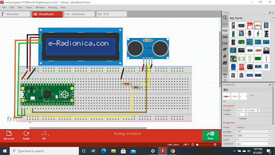
Interfacing HCSR04 Ultrasonic sound sensor and I2C 16x2 LCD with raspberry pi pico

Image
#Use this code for Display distance on the LCD  and if distance is less than 30 CM led indication & sound a buzzer from machine import I2C,Pin from lcd_api import LcdApi from pico_i2c_lcd import I2cLcd import utime import time buzzer=Pin(4,Pin.OUT) led=Pin(25,Pin.OUT) trigger =Pin(3,Pin.OUT) echo =Pin(2,Pin.IN) i2c=I2C(0,sda=Pin(0),scl=Pin(1),freq=400000) lcd=I2cLcd(i2c,0x27,2,16) lcd.move_to(0,0) lcd.putstr("Anokh Automation") lcd.move_to(0,1) lcd.putstr("Please Subscribe") time.sleep(2) lcd.clear() while True:     trigger.value(0)     utime.sleep_us(2)     trigger.value(1)     utime.sleep_us(5)     trigger.value(0)          while echo.value() == 0:         signaloff = utime.ticks_us()     while echo.value() == 1:         signalon=utime.ticks_us()     timepassed=signalon-signaloff     distance = (timepassed *0.0343)/2     if distance <30:         buzzer.toggle()         led.toggle()     else:         led.value(0)         buzzer.off()     print("The dist

Interfacing Photo sensor(KY018) with Raspberry pi pico

Image
  from machine import Pin import utime #Pin 16 is configured with internal Pull Down resistor. The pin value will be 0(Low) #when if LDR sensor is not Detected Darkness. #If Pull Down is used,LDR Sensor should be between the GPIO and Vcc(3.3V) LDR_sensor= Pin(16, Pin.IN, Pin.PULL_DOWN) Light=Pin(25,Pin.OUT) # Continuously runs the code under the while loop. while True: # Below value should be 0 if use a low active relay  if LDR_sensor.value() == 1:     print("Sensor Detected Darkness")     print("Light is ON")     print(LDR_sensor.value())     Light.on()#change(Light.off) if use a low active relay  else:     print("Sensor Detected Brightness")     print(LDR_sensor.value())     print("Light is OFF")     Light.off()#change(Light.on) if use a low active relay     utime.sleep(0.5)