Posts

Showing posts from May, 2022

16 LED Chaser with Pic 16F877A Microcontroller

Image
  https://acrobat.adobe.com/link/review?uri=urn:aaid:scds:US:5b3da523-9228-3b61-9156-6f9d30dfa442 Open mikroC application. click New project-standard project. click next. provide a project name-LEDCHASER. project folder- choose a folder in your computer. select device- select a PIC microcontroller,Ex: p16F877A. select device clock-8.000000(8 Mega hz) click-next then click finish. type the C code on MicroC editor, as per below👇 after complete code ,click on Build button on editor. Open the proteus simulator and draw the circuit diagram as per above.👆   TRISB = 0x00; //all bits are initialized as output PORTB= 0x00; //by default all pin are LOW while(1)         {         PORTB =0b00000001 ;//0x01;         Delay_ms(100);         PORTB =0b00000010 ;//0x02;         Delay_ms(100);         PORTB = 0b00000100;//0x04;         Delay_ms(100);         PORTB = 0b00001000;//0x08;         Delay_ms(100);         PORTB = 0b00010000;//0x10;         Delay_ms(100);         PORTB = 0b00100000;//0x20;    

ON/OFF with Push button using PIC16F877A microcontroller

Image
 void main() {      trisb.f0=1;     // set port B 0 as an input      trisb.f1=1;     // set port B 1 as an input      trisb.f2=0;     // set port B 2 as an output      portb.f2=0;     //set default walue of port B is LOW      while(1)      {             if(portb.f0==1)  //button 1 pressed if value of port B 0 is equal to 1 or HIGH              {                 portb.f2=1;  //turn on the led.set the value of Port B2 to High             }             if(portb.f1==1) //button 2 pressed.if value of port B 1 is equal to 1 or HIGH             {                portb.f2=0;  //tum off the LED.set the value of Port B2 to Low             }      } }

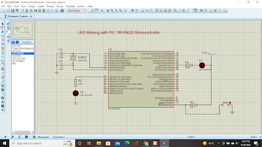
LED Blinking Project with PIC 18F45K22 Microcontroller in Micro C Programming

Image
 https://github.com/anokhramesh/LedBlink-with-PIC18F45K22 download link for MikroC https://drive.google.com/file/d/13pVa8EOkEv4mVRU1Ks4Row7WxD4stF33/view?usp=sharing code //Blinking 2 LED //anokhautomation //anokhramesh@gmail.com void main() {  TRISB = 0;//set direction to OUTPUT  TRISC5_bit = 0;  ANSELB = 0;  ANSELC = 0;  do{  LATB.B0 = 0;  LATC.B5 = 0;  Delay_ms(500);  LATB.B0=1;  LATC.B5=1;  Delay_ms(500);   } while(1); }

Jule thief Circuit

Image
 

Simple LED Forward Voltage Finder Circuit

Image
 

Dual Speed Switch less DIY drill

Image
 

Digital Clock with Arduino and RTC Module and P10 LEDmatrix

Image
  #include <Wire.h> #include "RTClib.h" #include <SPI.h>        #include <DMD.h>     #include <TimerOne.h>   #include "Arial_black_16.h" #include "Font_6x14.h" //-> This font only contains numbers from 0-9. Used only to display time. #define DISPLAYS_ACROSS 1 //-> Number of P10 panels used, side to side. #define DISPLAYS_DOWN 1 DMD dmd(DISPLAYS_ACROSS, DISPLAYS_DOWN); RTC_DS1307 rtc; //-> RTC Declaration int _day, _month, _year, _hour24, _hour12, _minute, _second, _dtw; int hr24; String st; char nameoftheday[7][12] = {"Sunday", "Monday", "Tuesday", "Wednesday", "Thursday", "Friday", "Saturday"}; char month_name[12][12] = {"January","February", "March", "April", "May", "June", "July", "August", "September", "October", "November", "December&quo

Auto Cut off 3.7 Volt Lithium Iron Battery Charger

Image
 

AC Motor Speed control with Smart Phone(Bluetooth Serial Application)

Image
Download and Install Serial Bluetooth Application from the link below https://drive.google.com/file/d/1fQAQ95veCc0LZDGkwJy_OXcFzulMHFOx/view?usp=sharing //Arduino Sketch #include <RBDdimmer.h> #include <SoftwareSerial.h> //#define mySerial  Serial SoftwareSerial mySerial(11,10); //connect RXD of Bluetooth module to D10 pin of Arduino and TXD of Bluetooth module to D11 of Arduino dimmerLamp dimmer(5); //Connect PWM pin of Robodyne dimmer to D5 pin of Arduino and Z0 pin to D2 pin of Arduino String msg;  void setup()   {     mySerial.begin(9600);      //USE_SERIAL.begin(19200);     dimmer.begin(NORMAL_MODE, OFF); //dimmer initialisation: name.begin(MODE, STATE)     delay(50);     dimmer.setPower(90);     delay(50);     dimmer.setState(ON);   } void loop() {          if (mySerial.available())   {           msg = mySerial.readString();       int buf = msg.toInt();       if (buf >9 && buf<=90)       {                                  if (dimmer.getState()==0)      

Electrical formulas

Image

SWITCH CASE

Image
                          SWITCH CASE https://github.com/anokhramesh/SWITCH-CASE-PRACTICAL Arduino Sketch int count = 0;// Variable name count default value is 0. void setup()  {   Serial.begin(9600);// select serial monitor baud rate 9600   pinMode(2, INPUT_PULLUP);// connect push button to digital pin 2    pinMode(3, OUTPUT);// connect LED-1 to digital pin 3    pinMode(4, OUTPUT);// connect LED-2 to digital pin 4    pinMode(5, OUTPUT);// connect LED-3 to digital pin 5   pinMode(6, OUTPUT);// connect LED-4 to digital pin 6   pinMode(7, OUTPUT);// connect LED-5 to digital pin 7   pinMode(8, OUTPUT);// connect LED-6 to digital pin 8 } void loop() {      Serial.print("Case  ");// print the value of count on serial monitor   Serial.println(count);      int val = digitalRead(2);// store the value of push button to variable 'val'   if(val == 0)// if value of val is equal to 0,add 1 to the value of count.   {     count = count + 1;   }   switch(count)//assign the count to s