Posts

16 LED Chaser with Pic 16F877A Microcontroller

Image
  https://acrobat.adobe.com/link/review?uri=urn:aaid:scds:US:5b3da523-9228-3b61-9156-6f9d30dfa442 Open mikroC application. click New project-standard project. click next. provide a project name-LEDCHASER. project folder- choose a folder in your computer. select device- select a PIC microcontroller,Ex: p16F877A. select device clock-8.000000(8 Mega hz) click-next then click finish. type the C code on MicroC editor, as per below๐Ÿ‘‡ after complete code ,click on Build button on editor. Open the proteus simulator and draw the circuit diagram as per above.๐Ÿ‘†   TRISB = 0x00; //all bits are initialized as output PORTB= 0x00; //by default all pin are LOW while(1)         {         PORTB =0b00000001 ;//0x01;         Delay_ms(100);         PORTB =0b00000010 ;//0x02;         Delay_ms(100);         PORTB = 0b00000100;//0x04;         Delay_ms(100); ...

ON/OFF with Push button using PIC16F877A microcontroller

Image
 void main() {      trisb.f0=1;     // set port B 0 as an input      trisb.f1=1;     // set port B 1 as an input      trisb.f2=0;     // set port B 2 as an output      portb.f2=0;     //set default walue of port B is LOW      while(1)      {             if(portb.f0==1)  //button 1 pressed if value of port B 0 is equal to 1 or HIGH              {                 portb.f2=1;  //turn on the led.set the value of Port B2 to High             }             if(portb.f1==1) //button 2 pressed.if value of port B 1 is equal to 1 or HIGH             {                portb.f2=0;  //tum off the LED.set ...

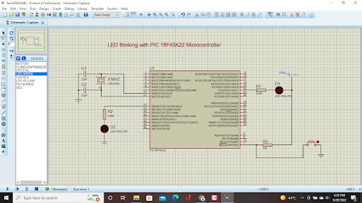
LED Blinking Project with PIC 18F45K22 Microcontroller in Micro C Programming

Image
 https://github.com/anokhramesh/LedBlink-with-PIC18F45K22 download link for MikroC https://drive.google.com/file/d/13pVa8EOkEv4mVRU1Ks4Row7WxD4stF33/view?usp=sharing code //Blinking 2 LED //anokhautomation //anokhramesh@gmail.com void main() {  TRISB = 0;//set direction to OUTPUT  TRISC5_bit = 0;  ANSELB = 0;  ANSELC = 0;  do{  LATB.B0 = 0;  LATC.B5 = 0;  Delay_ms(500);  LATB.B0=1;  LATC.B5=1;  Delay_ms(500);   } while(1); }

Jule thief Circuit

Image
 

Simple LED Forward Voltage Finder Circuit

Image
 

Dual Speed Switch less DIY drill

Image
 

Digital Clock with Arduino and RTC Module and P10 LEDmatrix

Image
  #include <Wire.h> #include "RTClib.h" #include <SPI.h>        #include <DMD.h>     #include <TimerOne.h>   #include "Arial_black_16.h" #include "Font_6x14.h" //-> This font only contains numbers from 0-9. Used only to display time. #define DISPLAYS_ACROSS 1 //-> Number of P10 panels used, side to side. #define DISPLAYS_DOWN 1 DMD dmd(DISPLAYS_ACROSS, DISPLAYS_DOWN); RTC_DS1307 rtc; //-> RTC Declaration int _day, _month, _year, _hour24, _hour12, _minute, _second, _dtw; int hr24; String st; char nameoftheday[7][12] = {"Sunday", "Monday", "Tuesday", "Wednesday", "Thursday", "Friday", "Saturday"}; char month_name[12][12] = {"January","February", "March", "April", "May", "June", "July", "August", "September", "October", "November", "December...